NTS8610

  • IEC61850-3 HV & IEEE 1613 Certified NTP Server & IEEE 1588 PTP Grandmaster
  • -40 to +85 °C Operating Temperature, IP40 Protection, and Up to 5100 m Altitude
  • MIL-STD-810F Certified for Environmental and Transportation Reliability
  • Dual Hot Swappable Power Modules with Wide Power Input Voltage Range
  • Full Redundancy Across Power, System, Network, and Link Layers
  • <40 ns PRTC-B/PTP, <50 μs NTP Accuracy, Calnex Verified
  • Excellent Holdover Performance: <0.5 μs/8 Hours / <72 μs/7 Days
  • Supports Power, Telecom, AVBTSN and Enterprise Profiles
  • Four Ethernet Ports: Two PTP-Capable Combo Ports, All Four NTP-Capable
  • Dual Media Combo Ports Enable Cost-Effective Copper/Fiber Deployment
  • Supports Multi-Constellation GNSS with Anti-Jamming and Anti-Spoofing
  • Optional Multi-Band GNSS SKU Supporting Up to 4 Concurrent Constellations
  • Antenna Fault Detection and Protection: Short Circuit and Disconnection
  • Configurable IRIG-B (TTL, Fiber, AM, RS-485), PPS I/O, and 10 MHz Outputs
  • Built-in 40×2 LCM for Display and Configuration
  • Streamlined Cable Management with Rear-Facing Connections
  • Standard 5-Year Warranty, Upgradeable to 10 Years
New
NTS8610

IEC 61850-3 HV & IEEE 1613 Certified NTP/PTP Grandmaster with -40 to +85 °C Operating Temperature

With an operating temperature range of -40 to +85 °C, and IEC 61850-3 HV and IEEE 1613 offering up to four times the EMC protection compared to rugged industrial-grade standards, the NTS8610 is engineered to operate reliably in environments exposed to electrical noise, temperature extremes, and radiated disturbances—ensuring uninterrupted performance and high system availability. The NTS8610 NTP Server and IEEE 1588 PTP Grandmaster is the world’s first solution fully certified to both IEC 61850-3 HV and IEEE 1613 standards, delivering exceptional resilience and precision in demanding applications such as power substations, telecommunications networks, automation systems, and enterprise infrastructure.


High Precision Timing

Rigorously tested by Calnex Solutions, a leader in network synchronization testing, the NTS8610 series delivers exceptional time precision, ensuring your power applications’ synchronization needs are met with the highest standards of accuracy. Featuring proven PRTC-B accuracy within 40 ns, IEEE 1588 PTP accuracy within 40 ns, and NTP accuracy within 50 μs, this Grandmaster guarantees precise time distribution across your network.


Superior Holdover Performance

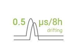
Holdover performance is critical to ensure uninterrupted and accurate time synchronization during loss of the primary time source. The NTS8610 series offers exceptional holdover stability, with a drift of less than 0.5 μs over 8 hours, and approximately 72 μs over 7 days, as validated by Calnex Solutions. When entering holdover mode, the system intelligently adjusts protocol attributes according to the active time profile (e.g., Power, Telecom), and proactively issues notifications via alarms and syslog to alert operators.


Versatile Profile Support

The Grandmaster supports a wide range of IEEE 1588 PTP profiles, making it suitable for deployment in power, telecom, AVB/TSN, and enterprise networks. For power utilities, it complies with IEEE C37.238-2011, C37.238-2017, and IEC/IEEE 61850-9-3:2016. Telecom synchronization is supported through ITU-T G.8265.1, G.8275.1, and G.8275.2 profiles. IEEE 802.1AS is also supported for time-sensitive networking in industrial and media environments. The Enterprise profile ensures interoperability across standard IT infrastructures. In addition, the Grandmaster supports SyncE for enhanced frequency stability in telecom applications.


GNSS Vulnerability Mitigation and Antenna Protection

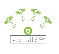
NTS8610 offers enhanced robustness and resilience against jamming and spoofing attacks. By receiving signals from multiple constellations on single or multiple bands for cross-verification, the system can detect spoofing attempts and switch to holdover mode if necessary. The Grandmaster also features comprehensive antenna vulnerability mitigation, detecting short and disconnected antennas to maintain system integrity. For added protection, a surge protector is available for purchase, safeguarding your equipment from electrical surges and ensuring the reliability of your timing infrastructure.


Comprehensive Redundancy

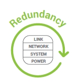
System redundancy is ensured through clustering, featuring IEC 62439-3 Parallel Redundancy Protocol (PRP) to provide network redundancy without data loss or downtime. Link redundancy is achieved via bonding and auto-failover functionality of combo ports, delivering resilient connectivity. Additionally, the NTS8610 series offers power redundancy with dual hot-swappable, detectable power modules supporting a wide input voltage range to safeguard against power failures.


Flexible Timing Input/Output

Modulated IRIG-B is ideal for long-distance transmission due to its resistance to signal degradation and compatibility with legacy equipment. Demodulated IRIG-B, available in TTL or RS-485 formats, offers higher precision, with IRIG-B RS-485 supporting distances up to 1200 meters. PPS and 10 MHz outputs are crucial timing signals in modern IEC 61850 power applications, providing precise synchronization essential for various grid operations. The NTS8610 series supports up to two selectable synchronization modules, offering options such as IRIG-B (TTL, AM, Fiber, RS-485), 1-PPS, and 10 MHz waveform input or output, with up to seven configurable channels. Additionally, IRIG-B RS-485 can be extended over long distances
using the ATOP SF63 serial-to-fiber converter via fiber-optic cable.


Ensuring Precision with Comprehensive Delay Compensation

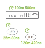
Compensation for antenna delay is essential because long antenna cables can introduce timing errors that affect the accuracy of synchronized operations. Similarly, output delay compensation for signals such as IRIG-B and PPS is vital, especially in systems with multiple IEDs connected. It is much easier and more efficient to compensate for cable delays at the Grandmaster level rather than at each individual IED, as not all IEDs support delay compensation. Handling these adjustments centrally at the Grandmaster guarantees that all connected devices operate in perfect sync, optimizing the performance and coordination of critical substation operations.


APPLICATION CASE

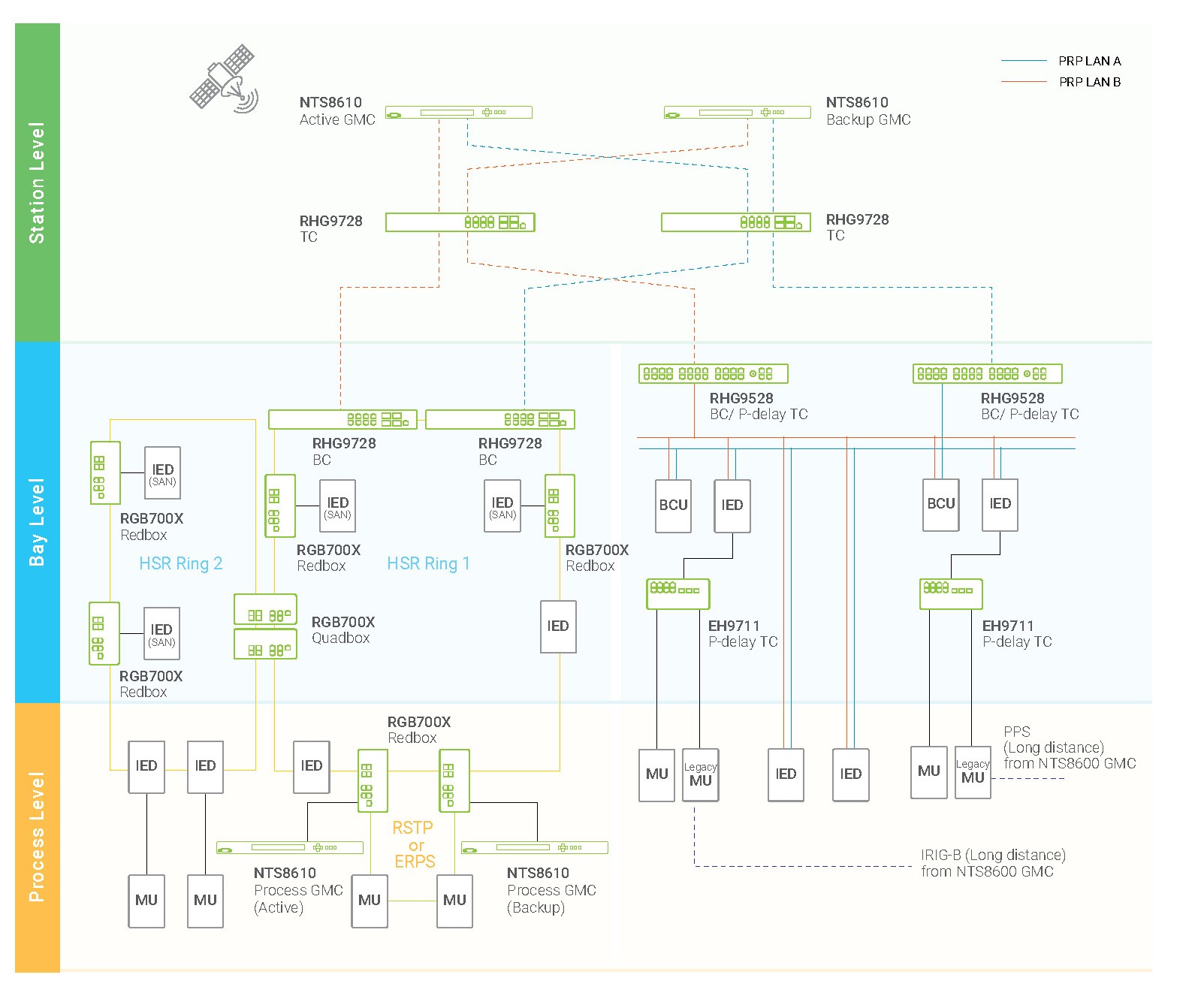
IEEE 1588 in Power Networks: Precision Time Synchronization and Time Redundancy
Two NTS8610 units in the station layer determine the Active and Backup GMC through BMCA. The Active GMC synchronizes to both GPS and GNSS satellite systems and transmits via IEC 62439-3 PRP to two power domains composed of PRP and HSR networks. According to IEC 61850-9-3 and IEEE C37.238-2017, the total end-to-end budget is 1us, with GMC being 250ns. The NTS8610 achieves superior accuracy of <40ns, reserving more budget for other devices. For early MU devices that rely on 1PPS or IRIG-B for synchronization, the NTS8610 offers 1PPS, IRIG-TTL, IRIG-B AM, IRIG-B RS-485, and RS-485 to fiber-optics by SF-63 for long-distance transmission and delay compensation.

The HSR network provides zero-packet-loss redundancy but also increases latency. Devices in the process layer require more precise timing. When the end-to-end budget cannot be met, a GMC must be deployed to aid in accurate timing for critical devices. The NTS8610, certified to IEC61850-3 HV & IEEE 1613, operates reliably in harsh process layer environments, providing precise synchronization.

In addition to the NTS8610, our timing solution for power substations also includes BC or TC of RHG9728 and RHG9528, P-Delay TC of EH9711, HSR Redbox, and Quadbox of RGB700X. Check our website for more detailed information on these products.
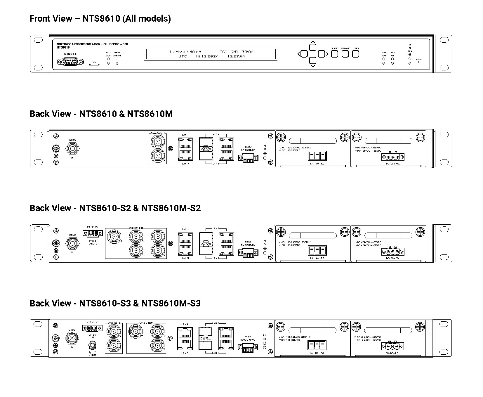


CONNECTORS

Environmental Limits
Operating Temperature-40°C to +85°C (-40°F to 185°F)
Storage Temperature-40°C to +85°C (-40°F to 185°F)
Operating Altitude5100m
Ambient Relative Humidity5% to 95% (Non-condensing)
Power Supply 
DC ModuleRated Supply Voltage: ±24 – ±60 VDC
Input Voltage Range: ±20 – ±66 VDC
AC ModuleRated Supply Voltage:
110 – 240 VAC, 50/60 HZ
110 – 250 VDC
Input Voltage Range:
85 – 264 VAC, 50/60 HZ
88 – 300 VDC
Power ConsumptionApproximately 15 W (Typical)
Approximately 20 W (Max)
Physical Characteristics
HousingSPCC w/Zinc Plated Body + Aluminum cover IP40 Metal Housing
Dimension (W x H x D)440 x 300 x 44
Chassis made of 1 mm SECC Sheet
Weight3.9 KG Max
Installation1U Rackmount
Functions & Protocols
ProtocolsNetwork
Synchronization
RFC 1119 (NTPv2) Server
RFC 1305 (NTPv3) Server
RFC 5905 (NTPv4) Server
RFC 1769 (SNTPv3) Server
RFC 2030 (SNTPv4) Server
Network ProtocolsVLAN (IEEE 802.1q) filtering/tagging
IEEE 802.1p QoS
DSCP
IPv4, IPv6
TCP, UDP
DHCP Client
TACAS+/ RADIUS
RedundancyDevices Clustering (NTP Only)
PRP (IEC 62439-3)
Bonding – Active & Backup
Bonding -- LACP
Combo Ports
ManagementHTTP, HTTPS
SNMP v1/v2,v3
SSH/ Telnet (CLI), could be enabled/disabled
Console CLI
Estimated Time Accuracy
GNSS Status
Power Status
PTP & NTP Status
SD/MMC Backup & Restore
Event & AlarmEvent Log
Syslog
Relay & Alarm Management
SNMP Trap
System Modes 
GNSS Locked ModeSynchronizes time with GNSS signals for high accuracy
Holdover ModeMaintains time using the OCXO clock after GNSS is unavailable
Free Run ModeOperates independently using RTC as the time source along with the OCXO clock
IEEE1588 Profiles 
DefaultIEEE 1588V2 (PTPv2)
Default UDP (IEEE1588-2008 Annex D and J)
Default 802.3 (IEEE1588-2008 Annex F and J)
PowerIEC/IEEE61850-9-3-2016 Power Utility Profile
IEEE C37.238-2011 Power Profile, with VLAN support
IEEE C37.238-2017 Power Profile, with VLAN support
TelecomITUT-G.8265.1 Frequency
ITUT-G.8275.1 Phase/Time
ITUT-G.8275.2 Phase/Time
AVBTSN802.1AS Profile
EnterpriseEnterprise Profile
*Media Broadcast
(In Development Plan)
SMPTE ST 2059-2
AES67 Media Profile
Frequency 
OscillatorAdvanced managed OCXO, with temperature drifting compensation
LCD Display & Control Buttons
LCD SpecCharacter Display LCD 40x2
5x8 Dots Includes Cursor
LCD Operating Temperature Range: -20°C to 70°C
LCD Over-Temperature Protection
Control ButtonsUp, Down, Left, Right, Menu, Enter, Back
Electrical Input/ Output Drive Levels
1PPS/IRIG-B TTL Output5VDC 20 mA TTL compliant
Modulated IRIG-B Output5Vp-p, 3.3:1 ratio, AM, Sinewave
1PPS/IRIG-B TTL Input5VDC HCMOS, >2.0V High <0.8V Low
Modulated IRIG-B Input1Vp-p to 8 Vp-p, ratio 3.3:1, AM
IRIG-B Fiber TTL820nm, Different fiber size: 50/125um, 62.5/125um, Output Driver Typ. 13.1uW
IRIG-B RS485 Input/Output±5 VDC IRIG-B Half-Duplex; 32 Transceivers Max. a bus
Sync Module – S3 
Sync1 ~ Sync2Two configurable output channels (coaxial BNC (F) connector):
1. 1PPS/PPM/PPH Output (Square Wave, configurable pulse width)
2. IRIG-B TTL Output (Support IEEE 1344 and C37.118.1)
3. AFNOR French Time Code Output
4. ASCII Timestamp Output*
Sync3One configurable output channel (Sync 3, coaxial BNC (F) connector):
1. 1PPS/PPM/PPH Output (Square Wave, configurable pulse width)
2. IRIG-B TTL B000~B007 Output (Support IEEE 1344 and C37.118.1)
3. IRIG-B AM B120~B127 Output (Support IEEE 1344 and C37.118.1)
4. AFNOR French Time Code
5. ASCII Timestamp Output*
Sync4One configurable input channel (coaxial BNC (F) connector):
1. IRIG-B TTL B000~B007 Input (Support IEEE 1344 and C37.118.1)
2. 1PPS input
3. AFNOR French Time Code TTL Input
Sync5One configurable modulated input channel (coaxial BNC (F) connector):
1. IRIG-B AM B120~B127 Input (Support IEEE 1344 and C37.118.1)
2. Modulated AFNOR French Time Code Input
Sync6One configurable input/output channel (Sync 6, TB3 connector):
1. IRIG-B RS-485 B000~B007 Input (Support IEEE 1344 and C37.118.1)
2. IRIG-B RS-485 B000~B007 Output (Support IEEE 1344 and C37.118.1)
3. AFNOR French Time Code RS-485 Input
4. AFNOR French Time Code RS-485 Output
Sync7One configurable output channel (ST (F) connector):
1. 1PPS/PPM/PPH Output (Square Wave, configurable pulse width)
2. IRIG-B TTL Output (Support IEEE 1344 and C37.118.1)
3. AFNOR French Time Code Output
4. ASCII Timestamp Output*
Sync Module – S2 
Sync1 ~ Sync2Two configurable output channels (coaxial BNC (F) connector):
1. 1PPS/PPM/PPH Output (Square Wave, configurable pulse width)
2. IRIG-B TTL Output (Support IEEE 1344 and C37.118.1)
3. AFNOR French Time Code Output
4. ASCII Timestamp Output*
Sync3 ~ Sync5Three configurable output channels (Sync 3 - Sync 5, coaxial BNC (F) connector):
1. 1PPS/PPM/PPH Output (Square Wave, configurable pulse width
2. IRIG-B TTL B000~B007 Output (Support IEEE 1344 and C37.118.1)
3. IRIG-B AM B120~B127 Output (Support IEEE 1344 and C37.118.1)
4. AFNOR French Time Code
5. ASCII Timestamp Output*
Sync6One configurable output channel (Sync 6, TB3 connector):
1. IRIG-B RS-485 B000~B007 Output (Support IEEE 1344 and C37.118.1)
2. AFNOR French Time Code Output
I/O 
Console1x DB9 Serial Console Port
SD slot1x micro-SD slot
Relay - Alarm ContactThree Pins Relay with NC, NO and GND.
Rated Operational Voltage: 24-250 VDC
Continuous carrier: 3 A max. 75VA max
Dropout Time: ≤ 6 ms typical
Pickup time: ≤ 8 ms
Network Interface 
Ethernet StandardsIEEE 802.3 10BaseT
IEEE 802.3u 100BaseT(X)
IEEE 802.3ab for 1000BaseT(X) IEEE 802.3u for 100Base-FX IEEE 802.3z
for 1000Base-X
Gigabit Ethernet PortsTwo Combo ports, 2x 10/100/1000BASE-T(X) RJ45 or 2x 100/1000 Base-X SFP
Support Synchronous Ethernet (SyncE) per ITU-T G.8261 ITU-T, G.8262 and G.8264
ESMC), PTP-Capable and NTP-Capable
Management Port2 x 10/100 BASE-T(X) RJ45, NTP-Capable
Proven Clock Accuracy (Relative to UTC)
1PPS±40 ns Peak *1
Demodulated IRIG-B±40 ns Peak *1
Modulated IRIG-B AM±1 μs Peak *1
RS-485 IRIG-B±100 ns Peak *1
PTP Timestamp±40 ns Peak *1
NTP Timestamp±50 us Peak , ±40 us Average *1
Holdover accuracy - OCXO<0.5 us / 8 hours / <72 us / 7 days *2
*1. Device locked to satellites for at least 24 hours.
*2. Device locked to satellites for at least 48 hours before holdover
Antenna specification (Accessories)
GNSS Antenna
(59902521G)
GNSS Receiver: GPS L1, GLONASS L1, BeiDou B1, Galileo E1
LNA Gain: 40dB min
Weather-Proof Housing: IP69K
Operating and Storage Temperature: -40°C - 85°C
ESD: ±15KV Air Discharge
Mechanical Size: 66.5 mm dia. x 21 mm H
MIL-STD-810F
Supply Voltage Range: 2.5 to 16VDC
GPS Antenna
(59902531G)
GNSS receiver: GPS L1, Galileo E1
LNA Gain: 40dB min
Weather-Proof Housing: IP69K
Operating and Storage Temperature: -40°C - 85°C
ESD: ±15KV Air Discharge
Mechanical size: 66.5 mm dia. x 21 mm H
MIL-STD-810F
Supply Voltage Range: 2.5 to 16VDC
Multi-band GNSS Antenna
(59902851G)
For NTS8610M series
GNSS Receiver:
GPS: L1C/A, L2C or L5
Galileo: E1, E5a or E5b
BeiDou: B1I, B2I or B2a
GLONASS: L1OF
NavIC: L5
LNA Gain: 37dB min
Weather-Proof Housing: IP69K
Operating and Storage Temperature: -40°C - 85°C
ESD: ±15KV Air Discharge
Mechanical Size: 66.5 mm dia. x 21 mm H
MIL-STD-810F
Supply Voltage Range: 2.5 to 16VDC
Maximum Antenna Cable LengthAntenna cable:
Without amplifier:
LMR-400: 150M CFD-200: 50M RG58A/U: 25M
With Amplifier:
LMR-400: 250M CFD-200: 80M RG58A/U: 50M
Maximum Sync-Out Cable LengthRG58 A/U Sync-Out cable:
1PPS, 10 MHz, IRIG-B TTL: 150M
IRIG-B AM: 150M @ 1K impedance, 300M @ 10K impedance
IRIG-B RS485: 1200M
IRIG-B Fiber TTL: 1500M
IRIG-B RS-485 with SF63 Fiber optic 2KM
Multiple Band - GNSS Receiver Specifications
GNSS Input ports1x GNSS Input; TNC (F) - active Antenna
GNSS Module specific InformationMulti-Constellation Supported:
GPS: L1C/A, L2C or L5
Galileo: E1, E5a or E5b
BeiDou: B1I, B2I or B2a
GLONASS: L1OF
NavIC: L5
Maximum Concurrent Constellation: 4
Leap Second: Supported
Sensitivity for GPS + GLONASS + Galieo + BeiDou
• Tracking: -167 dBm
• Reacquisition: -160 dBm
• Cold Start: -148 dBm
• Hot Start: -157 dBm
Acquisition TimesCold Start: <24 seconds
Warm Start: <2 seconds
Antenna Requirements3.3 V, <50 mA
Minimum gain = 6dB; Maximum gain + Cable Attenuation ≤ 30dB
GNSS Vulnerability MitigationJammingSupport Detection, Warning and Switch to OCXO Holdover
SpoofingSupport Detection, Warning and Switch to OCXO Holdover (GNSS Antenna Only)
Antenna Vulnerability
Mitigation
Antenna Cable ShortSupport Detection, Warning and Switch to OCXO Holdover Mode
Antenna DisconnectionSupport Detection, Warning and Switch to OCXO Holdover Mode
Single Band - GNSS Receiver Specifications
GNSS Input ports1x GNSS Input; TNC (F) - active Antenna
GNSS Module specific InformationMulti-Constellation Supported: GPS L1, GLONASS L1, BeiDou B1, Galileo E1
Maximum Concurrent Constellations: 3
Leap Second: Supported
Sensitivity for GPS:
• Tracking: -166 dBm
• Reacquisition: -160 dBm
• Cold Start: -148 dBm
• Hot Start: -160 dBm
Acquisition TimesCold Start: <45 seconds
Warm Start: < 7 seconds
Antenna Requirements3.3 V, <50 mA
Minimum gain=5dB; Maximum gain + Cable Attenuation ≤ 40dB
GNSS Vulnerability MitigationJammingSupport Detection, Warning and Switch to OCXO
Holdover
SpoofingSupport Detection, Warning and Switch to OCXO
Holdover (GNSS Antenna Only)
Antenna Vulnerability
Mitigation
Antenna Cable ShortSupport Detection, Warning and Switch to OCXO
Holdover Mode
Antenna DisconnectionSupport Detection, Warning and Switch to OCXO
Holdover Mode
Technical Specifications 
Model NameNTS8610 Series (See ordering information)
CertificationStandard
Shock
Drop
Vibration
MIL-STD-810G Method 516.5
MIL-STD-810F Method 516.5
MIL-STD-810F Method 514.5 C-1 & C-2
RoHS2Yes
MTBF20 years
Warranty5 years / Upgradable to 10 years
TestItemTestValueLevel
IEC 61000-4-2ESDContact Discharge
Air Discharge
±8KV
±15KV
4
4
IEC 61000-4-3RSEnclosure Port10(V/m), 80-3000MHz
20(V/m), 80-1000MHz
3
IEC 61000-4-4EFTAC Power Port
DC Power Port
Signal Port
±4.0 kV
±4.0 kV
±4.0 kV
4
4
Special
IEC 61000-4-5SurgeAC Power Port
AC Power Port
DC Power Port
DC Power Port
Signal Port
Line-to Line±2.0 kV
Line-to Earth±4.0
kV
Line-to Line±1.0 kV
Line-to Earth±2.0 kV
Line-to Earth±4.0 kV
4
4
4
3
4
IEC 61000-4-6CS0.15-80MHz10V rms 0.15-80MHz, 80% AM3
IEC 61000-4-8PFMF(Enclosure)100A/m continuous, 1000A/m (3s)5
IEC 61000-4-11DIPAC Power Port30% Reduction (Voltage Dips), 1 Period
60% Reduction (Voltage Dips), 50 Period
100%, Reduction (Voltage Interruptions), 5 Period
100% Reduction
(Voltage Interruptions), 50 Period
-
IEC 61000-4-12Ring wave
immunity
AC Power Port
AC Power Port
DC Power Port
DC Power Port
Signal Port
Line-to Line±1.0 kV
Line-to Earth±2.0 kV
Line-to Line±1.0 kV
Line-to Earth±2.0 kV
Line-to Earth±4.0 kV
3
3
3
3
3
IEC 61000-4-16Main Frequency
Voltage
DC Input Port
Signal Port
30V Continuous, 300V 1s
4
4
IEC 61000-4-17RippleDC Input Port10% of unit3
IEC 61000-4-18Damped
Oscillatory
AC Power Port2.5KV common,
1KV differential mode @ 1MHz
3
Signal Port Telecommunication
Port
2.5KV common,
1KV differential mode @ 1MHz
3
IEC 61000-4-29DC Voltage Dips
& Interruptions
DC Input Port30% Reduction (Voltage Dips): 0.1 sec
60% Reduction (Voltage Dips): 0.1 sec
100% Reduction
(Voltage Interruption): 0.05 sec
-
IEC 60255-22-11 MHz burst
immunity
AC Power Port
AC Power Port
DC Power Port
DC Power Port
Signal Port
Line-to Line±1.0 kV
Line-to Earth±2.5 kV
Line-to Line±1.0 kV
Line-to Earth±2.5 kV
Line-to Earth±1.0 kV
-
Regulatory Approvals 
SafetyLVD EN 62368-1 (Certified Operating Temperature: 75°C), IEC 60255-5
EMCFCC(EMI): FCC Part 15, Subpart B, Class A CE(EMI): EN 55032, EN 61000-6-4, Class A
EN 61000-3-2 (Current Harmonics) EN 61000-3-3 (Voltage Flicker) CE(EMS): EN 55035,
EN 61000-6-2
CE(GNSS): EN 303 413. EN 301 489-19
IEC 60255-25, IEC 60255-22-1
Power AutomationIEC 61850-3, IEEE 1613

NTS8610 - Optional Accessories – External Power Adapter and Converter

Model NamePart NumberDescription
SDR-75-2450500752240001GDin-rail Power Supply/T; 88 - 264 VAC/124 - 370 VDC to 24 VDC 3.2 A; 75W
SF63 SeriesSee ATOP SF63 DatasheetIndustrial Serial to Fiber Media Converter for Long Distance Transmission

NTS8610 - Optional Accessories – SFP Modules

Model NamePart NumberDescription
AXFD-1314-0523522AXFD1314001GSFP Transceiver, 155 Mbps, 1310 nm, multi-mode, 2 km,
-40°C to +85°C, DDMI
AXFD-1314-0553522AXFD1314011GSFP Transceiver, 155 Mbps, 1310 nm, single-mode, 30 km,
-40°C to +85°C, DDMI
AXGD-5854-0513522AXGD5854001GSFP Transceiver, 1250 Mbps, 850 nm, multi-mode, 550 m, 3.3V,
-40°C to +85°C, DDMI
AXGD-1354-0523522AXGD1354001GSFP Transceiver, 1250 Mbps, 1310 nm, multi-mode, 2 km, 3.3V,
-40°C to +85°C, DDMI
AXGD-1354-0533522AXGD1354011GSFP Transceiver, 1250 Mbps, 1310 nm, single-mode, 10 km, 3.3V,
-40°C to +85°C, DDMI
AXGD-3354-0593522AXGD3354001GSFP Transceiver, 1250 Mbps, 1310 nm, single-mode, 40 km, 3.3V,
-40°C to +85°C, DDMI

NTS8610 - Optional Accessories – Antenna and Sync-Out Cables

Model NamePart NumberDescription
Antenna Cable
20M RG58 A/U
50802221GTNC-Male to TNC-Male 20M RG58 A/U Antenna Cable.
Antenna Cable
30M CFD-200
50802211GTNC-Male to TNC-Male 30M CFD-200 Antenna Cable.
Antenna Cable
Custom-Length
RG58 A/U
Made to OrderTNC-Male to TNC-Male Custom-Length RG58 A/U Antenna Cable. Specify
desired length when ordering. Supports up to 25 m without amplifier, or 50 m
with amplifier.
Antenna Cable
Custom-Length
CFD-200
Made to OrderTNC-Male to TNC-Male Custom-Length CFD-200 Antenna Cable. Specify
desired length when ordering. Supports up to 50 m without amplifier, or 80 m
with amplifier.
Antenna Cable
Custom-Length
LMR-400
Made to OrderTNC-Male to TNC-Male Custom-Length LMR-400 Antenna Cable. Specify
desired length when ordering. Supports up to 150 m without amplifier,
or 250 m with amplifier.
Sync-Out Cable
(IRIG-B/PPS TTL)
Made to OrderBNC-Male to BNC-Male Custom-Length RG58 A/U Antenna Cable. Specify
desired length when ordering. Supports up to 150 m.

NTS8610 - Optional Accessories – Antenna, Amplifier, Surge Protector and Mounting Kits

Model NamePart NumberDescription
Single Band
GNSS Antenna
Package
59902521GHigh Gain Multi-Constellation TNC-Female Antenna
(See the Antenna Specifications section above for a spec summary)
Single Band GPS
Antenna Package
59902531GHigh Gain GPS L1 TNC-Female Antenna
(See the Antenna Specifications section above for a spec summary)
Anti-Jamming
GNSS Antenna
59902661GHigh Gain Anti-Jamming Multi-Constellation TNC-Female Antenna
(See the Antenna Specifications section above for a spec summary)
Multi Band GPS
Antenna Package
59902851GHigh Gain Multi-Constellation and Multi-bands TNC-Female Antenna
(See the Antenna Specifications section above for a spec summary)
RF Amplifier70100000000092GInline TNC-Female RF (1559-1610MHz) Amplifier 25dB with Supply Volts
3-10 VDC and 10 mA
Surge Protector70100000000093GSOCAA 4LTJ10TP001 – TNC-Female 10 kA Surge protection device
Advanced Surge
Protector
70100000000094GPhoenix Contact CN-UB-280DC-BB – N-Type 20 KA Surge protection device
including Two N-type Male to TNC Female
Mounting Kits70100000000095GThe Antenna Mounting Kit Includes an L-bracket, Mount Adapter and Ground
Plane. (See NTS8610 User Manual for More Details)

NTS8610 - Power Modules

Model NamePart NumberDescription
NTS8610-DC1P1NTS8610DC01GRated Supply Voltage: ±24 – ±60 VDC
Input Voltage Range: ±20 – ±66 VDC
NTS8610-AC1P1NTS8610AC01GRated Supply Voltage:
110 – 240 VAC, 50/60 Hz
110 – 250 VDC
Input Voltage Range:
85 – 264 VAC, 50/60 Hz
88 – 300 VDC

NTS8610 - Main core and Modules

Model NamePart NumberGNSS ModuleSync-OutPower Modules
NTS86101P1NTS86100001GSingle BandN/ASupport Two Hot Swappable
Power Modules.
2x NTS8610-AC or
2x NTS8610-DC or
1x NTS8610-DC +
1x NTS8610-AC
NTS8610M1P1NTS8610M001GMulti-BandsN/A
NTS8610-S21P1NTS86100002GSingle BandS2
NTS8610M-S21P1NTS8610M002GMulti-BandsS2
NTS8610-S31P1NTS86100003GSingle BandS3
NTS8610M-S31P1NTS8610M003GMulti-BandsS3

Firmware

Version Name Time Size Download
v1.11 NTS8610 Series Firmware(compatible with MIB v100) 2025-10-31 21.2 MB

Datasheet

Version Name Time Size Download
v1.0 NTS8610 Series Datasheet EN 2025-10-31 1.35 MB

Manual

Version Name Time Size Download
v1.00 NTS8610 Series User Manual 2025-10-31 6.76 MB

Hardware Installation Guide

Version Name Time Size Download
v1.0 NTS8610 Series Hardware Installation Guide 2025-10-31 21.91 MB

MIB

Version Name Time Size Download
v100 NTS8610 Series MIB(compatible with FW v1.11) 2025-10-31 16.35 KB

STP/DXF drawings

Version Name Time Size Download
NTS8610 Series STP file 2025-10-31 33.34 MB

Test reports

Version Name Time Size Download
NTS8610 Declarations of Conformity 2025-10-31 347.14 KB
NTS8610 Series CE EMC Certification 2025-10-31 11.06 MB
NTS8610 Series CE LVD EN62368-1 Certification 2025-10-31 7.53 MB
NTS8610 Series CE RED Certification 2025-10-31 5.74 MB
NTS8610 Series FCC Certification 2025-10-31 1.98 MB
NTS8610 Series IEC 60255 2025-10-31 1.63 MB
NTS8610 Series IEC 61850-3 & IEEE1613 2025-10-31 20.88 MB

I have read and agree to the Privacy Policy (art.13 and 14 of the GDPR - EU Regulation 2016/679).