January 19, 2022
Simulated telecom site for 5G chip testing.

How we used RHG9528 to construct a time-synchronized site with multiple base stations.
INDUSTRY
Telecom
CHALLENGE
In order to reduce offsite testing resources, the customer, a leading chip manufacturer, wants to set up onsite time-synchronized base stations, simulating telecom applications to perform preliminary onsite chip testing.
In the real world, chip applications may include 5G signal switching from station A to station B, or simultaneous communication with 2 or more stations, with all base stations synchronizing with satellite time through a grandmaster clock. So for the test site, the customer requires time error between base stations to be < 3 μs. With multiple time-synchronized test stations, the manufacturer can verify their chips for station switching and synchronized processing.
Architecture for the test site network:
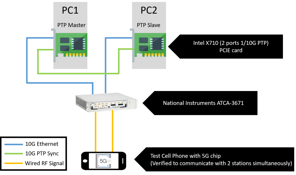
Scenario 1: Two base stations (1-to-1 sync)
– PCs (PCIE cards): Simulated base stations. One acts as the master and the other a slave for time synchronization.
– NI signal converter: Unlike real telecom base stations, PCs transmit Ethernet data (blue lines). So, a converter is needed to transform the network signals into wired 5G RF signals (orange lines) that cell phones can receive.
– Test cell phone with 5G chip
Site verification:
A “golden sample” is a 5G chip which has been externally verified as capable of simultaneous communication with two different base stations. This chip is placed in the test phone and receives signals from both base units at the same time. By comparing the lengths of subframes from both stations, time precision between the two base stations can be verified.
Post setup:
Once all base stations are confirmed as synchronized, the site can be used for testing newly developed 5G chips. A satisfactory chip in the test cell phone should be able to communicate simultaneously with both base stations, as well as switch from communicating with one station to the other.
Issue:
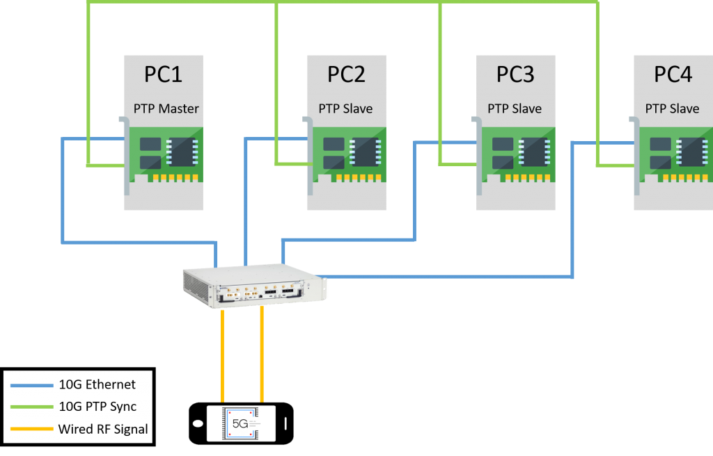
Scenario 2: Multiple base stations (1-to-many sync)
Currently, the time error for one-to-one time synchronization between 2 simulated base stations is less than 100 ns, but for one-to-many synchronization, the error will exceed 3 μs (acceptable time error).
SOLUTION
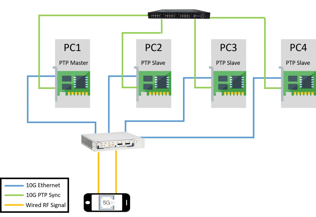
Scenario 3: Multiple base stations (1-to-many sync) with boundary clock
Prolonged time error occurs because too many PTP slaves are overwhelming the master PC. ATOP RHG9528, a hardware-based boundary clock with nanosecond-level accuracy, helps synchronize system time by acting as a slave to the master, but a master to the slave PCs. It reduces the synchronization loading for PC1 and ensures minimized latency overall, therefore enabling multi-station time synchronization for test scenarios where more than two base stations are required